Using
CSGUsing
CSG
Using
CSGUsing
CSG|
Introduction -CSG (Constructive Solid Geometry) |
||
|
MTOR provides functionality for CSG Boolean operations on geometric surfaces -- computed in the renderer. CSG stands for "Constructive Solid Geometry," allowing two, or more, objects (or groups of objects) to be combined in a number of ways, creating complicated geometry and special effects.
Using CSG requires that objects be specified as special CSG primitives. Then they must be grouped together and that group must have a CSG operation applied to it. Here's how . . .
|
||
|
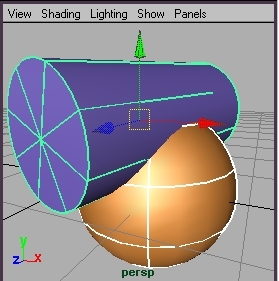
1 - Create Geometric CSG primitives |
||
|
First create two pieces of geometry in Maya, as seen here. (For best results the geometry should be a closed solid, with no open holes.) Next designate each geometric piece as a CSG primitve. Select the geometry and then from the RenderMan menu . . . Attributes-> CSG-> Primitve The objects at the base of a CSG hierarchy should always
be designated as CSG primitives. |
 |
|
|
2 - Group and Apply CSG Operation |
||
|
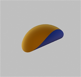
Group the two objects together. Now apply a CSG operation on the grouped node. Here we select our grouped node "groupCSG" and have applied . . . Attributes-> CSG -> Difference |
 |
|
|
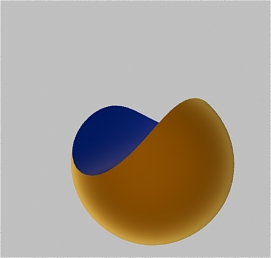
3 - Render "Difference" |
||
|
Render the scene. The final image give us a CSG difference, with the cylinder making a hole through the sphere. In this case the hole is made in the sphere since it is the first item in the group. If the cylinder was first, then the sphere would make a hole in the cylinder. An objects order in the hierarchy of the group determines how objects are subtracted. Note: The section the cylinder cuts away is shaded by the cylinder's shader. |
 |
|
|
4 - The "Intersection" |
||
|
Now apply a different CSG operator to the grouped
node: Now render. An object is formed from only the area that the objects both occupy. |
 |
|
|
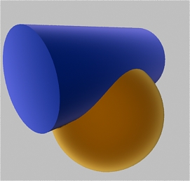
5 - The "Union" |
||
|
Now use the third operator: Render. An single object is created from the intersecting objects. Note: These two pieces of geometry are now "fused" together into one piece. This can be useful in cases where the fused geometry will be used to perform other CSG operations on other geometry. |
 |
|
|
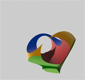
6 - Conclusion |
||
|
CSG are a powerful technique for the following reasons:
The image on the right was created by adding the
cylinder and sphere to a larger hierarchy of CSG operations. We'll
leave it as an exercise to the reader to figure out how this puzzling
geometric artifact was accomplished. |
 |
|
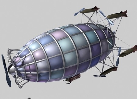
A Supplemental Airship Example. |
|
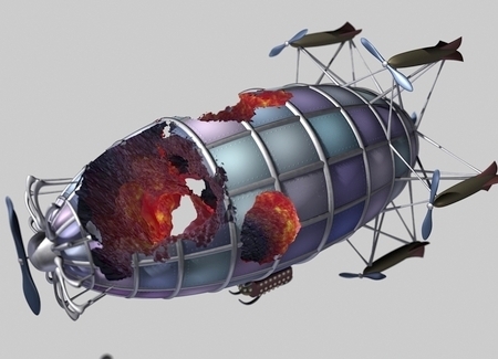
| Here we'll take a heavy model of an airship, group it, and apply CSG operations to it. We'll use multiple objects to poke holes into the airship. We'll apply displacement shaders to the intersecting objects to create explosion-type holes. It would be simple to animate these "explosions". Read along to get an idea of CSG's "explosive" potential. (The techniques are the same as used above, review above tutorial if needed.) | |
|
1 - The Airship |
|
|
This complicated model was grouped together and designated as a CSG primitive. |
 |
|
2 - The Geometry for the Holes |
|
|
Here are three separate pieces of geometry (deformed spheres), with special displacement shaders applied to them. Not only will the the holes appear jagged from the displacement, but a specially devised surface shader will give the appearance that are glowing inside. These three objects are also designated as CSG primitives. |
 |
|
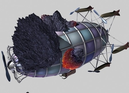
3 - The "Holes" Are Placed |
|
|
The "hole" geometry is placed where desired to the ship. |
|
|
4 - Everything is Grouped |
|
|
It's all grouped together and then a CSG "Difference" is applied to the grouped node (in this case its "CSG_Subtract"). The "Airship" node is positioned first in the group. Additional CSG primitives grouped here will be subtracted out of the ship (in this case "hole1", "hole2", and "hole3"). |
|
|
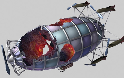
5 - The Airship is Rendered |
|
|
Now when the airship is rendered there are large gaping holes compromising its integrity. Congratulations! |
 |
|
Pixar Animation Studios
|