|
|
|
Introduction - Building a Layered Shader with Slim |
|
|
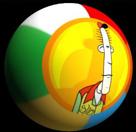
The layered shader is a powerful tool for constructing Slim Shading networks. The layered shader allows you to layer several different surface models over each other (i.e. blinn over metal over plastic, etc) using a variety of different compositing blends. In this tutorial, we will walk through the process of creating a layered shader by building a shading network of a Slim beach ball.
|
|
Creating a Layered Shader1 - Open the Tutorial Scene |
|
|
For this tutorial, open the following scene file : In this scene we have a ball and a MTOR coordinate system. We'll use the coordinate system to position a planar-Z projection on the ball. |
|
|
2 - Render the Scene |
|
|
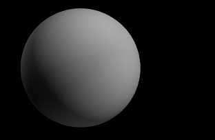
Render the scene from MTOR: RenderMan-> Render You should get a gray ball. This is the gray shader is the default color of the ball, just waiting for a new layered shader. |
|
|
3 - Create a Layer Shader |
|
|
Next we'll create a layer shader and build the first layer. Next create a layered shader. Open the layer in the
appearance editor by double-clicking it in the palette. Next add a layer by
clicking on the "Add Layer" button. ( Now connect a Matte
shading model to the new layer by clicking on the pull down menu ( |
|
|
4 - Construct a Layer for the Stripes |
|
|
Now we'll add a texture of beach ball stripes.
Open the matte in the Appearance editor, by clicking on the "Matte"
connection. ( With the Matte open, we'll connect an image file to the
SurfaceColor parameter. There we'll add a stripe texture. We can connect an
image file by switching the parameter's provider from "internal" (
|
|
|
Open the "Image File" into the appearance editor by clicking on the
ImageFile button.
With the ImageFile now open, open the file picker by clicking on the file
picker icon ( Next we must convert the texture. From the texture menu ( Now we'll attach an ST manifold to the ImageFile, applying our texture to the natural parameterization of the
object. To create the connection, select ST from the manifold pull-down
menu.( |
|
|
5 - Render the Ball with New Stripes |
|
|
Now display the Layer shader in the Graph Editor. This is a good way to see how
your shader is coming along. To do that, right-click on the layer node in the
palette and select: Call Graph-> Graph Children It should be similar to the example on the right. Try rendering the nodes to make the colored icons appear, if you haven't done so already. To do that, select the nodes by dragging a lasso around them (Red boxes will appear around selected nodes), and type "r" (for render icons). Now render from the RenderMan menu, like we did above. You should get an image similar to the one on the right, a ball with stripes. This completes the first layer. |
|
|
5 - Add a New Layer |
|
|
We've successfully added the stripes. Now we'll project an image of Slim onto the ball. For the next step we'll add a second layer. We'll use the second layer to project an image of Slim over the stripes. To add a new layer, open the Layer in the appearance editor and
clicking the add layer button ( Notice the "Over" pull-down menu, which provides a variety of different blends. In our case, the default "over" is fine. |
|
|
6 - Construct the Second Layer |
|
|
To start building the second layer, open the new Matte in the appearance editor. With the Matte open, add a new ImageFile to the
SurfaceColor parameter from the color pull-down menu ( |
|
|
Open the new ImageFile in the appearance editor. Now we'll add the texture
of Slim, and attach a Projection manifold.
With the ImageFile now open, open the file picker by clicking on the file
picker icon ( Next we must convert the texture. From the texture menu Finally, connect a Projection manifold from the pull-down menu ( |
|
|
Open the Projection manifold in the appearance editor, and we'll configure a
planar-Z projection.
The default settings are basically all we need for a planar-Z projection. However, we could also create other types of projections (spherical, box, cylindrical, etc.) by changing the settings. Next, we must complete the projection by attaching a SurfacePoint manifold to the Projection. This allows us to define a coordinate system for the projection. You can connect one from the Manifold pull-down menu. We'll use the SurfacePoint to define where the projection is placed in the scene, by filling in the name of a coordinate system. |
|
|
Finally, open the SurfacePoint in the appearance editor.
With the SurfacePoint open, enter the name of the coordinate system into the
Space parameter (see image on the right). We want to call our coordinate system "SlimShape",
so we'll enter that, we'll also add a little syntax that will make things
easier. So we enter: Next we need to rename our coordinate system in the scene. It has its default name. Generally it's a good idea to rename coordinate systems to something more sensible. Select the coordinate system in Maya and rename its shape node to "SlimShape" like the image shows. Notice that the SurfacePoint requires the shape name and not the object name. |
|
|
7 - The Second Layer so Far - Needs Transparency |
|
|
Take a look at the shading network in the graph editor, like we did above. We can see the second layer. However, if you render the swatch of the layer, the top node in the hierarchy, we can see that the second layer completely covers the first layer. To fix that we'll add transparency to the second layer, so the stripes of the beach ball are visible. Then we'll be finished with the shader. |
|
|
8 - Adding Transparency to the Second Layer |
|
|
Open the open the top node of the second layer (the matte) in the appearance editor. Connect a FloatToColor to the SurfaceOpacity like we did above (by switching the provider from internal to connection and then selecting FloatToColor from the pull-down menu). |
|
| Next open the float to color and add an ImageFile float from the pull-down menu. |
|
|
Open the ImageFile float, and then select "slim.tif"
from the images directory (by using the file picker as shown above).
Notice that we're using the alpha channel of the original texture. The Channel parameter determines which channel we take from the image (R, G, B, luminance, or alpha, to name a few). By using the ImageFile Float (as opposed to the ImageFile Color), we can select any channel we want. Now remember to convert the texture to a file format PRMan can read. From the texture menu select: Finally, connect the first projection manifold from the pull-down menu. In this case our original projection was called "Projection_0" and we can select that from the bottom of the manifold pull-down menu. By sharing the projection node we can control the placement of both images (defining color and alpha transparency) with a single projection and coordinate system. |
|
|
9 - The Final Shading Network |
|
|
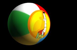
Looking at the shading network, we can see the two layers. The first layer, with
the stripes, is relatively simple. The second layer is slightly more complex,
with two image files, one for color and the other for opacity, being controlled
by one shared projection.
When we render the scene we see the texture of Slim placed over the stripes of the beach ball. |
|
|
10 - Exercise: Adding a Third and Fourth Layer |
|
|
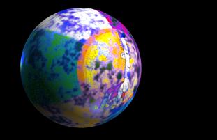
As an exercise, try adding another layer, with its own manifold. In the image here, a metal has been laid on top of the first two layers and a fractal has been used to modify the opacity. There's many different effects that can be created using layered
shaders. |
|
|
Pixar Animation Studios
|