|
|
|
|
|
Introduction - Creating Projections |
||
|
Projection techniques can be used to apply 2D textures onto 3D objects. There are a variety of different ways to map a projection, but all projections require a point in 3D space to define the origin of the projection. MTOR uses objects called coordinate systems to define the influence of projections. (For more info about using coordinate systems refer to MTOR Coordinate Systems under the Shader Concepts section.) In this lesson, we'll cover the basics of using coordinate systems to set up planar-Z projections. The creation of a projection requires two things:
|
|
|
Creating A Projection1 - Open the Scene for the Projection |
||
|
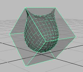
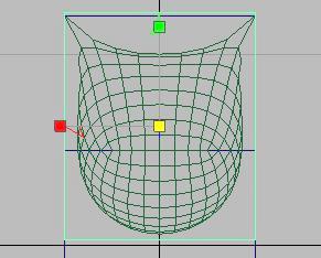
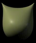
For this example, we'll project a texture on a simple subdivision surface. Open the scene: mtor/ scenes/ kitty-projections/ kitty.ma In our simple model, we'll be projecting a face onto our model. To do this, we'll create a MTOR coordinate system. We will use the coordinate system to place the projection onto the model. |
|
|
|
2 - Setting up a MTOR Coordinate System #1 |
||
|
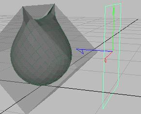
We're going to create a coordinate system that we will place in front of the model to project the image of the face. Renderman -> New Coordinate System The coordinate system has arrows visualizing its coordinates. Note the positive Z direction is defined by the blue arrow in the image, and this should be pointed in the direction of the projection. Place the coordinate system in front of the object, as in the image. Now fit the coordinate system snugly around the area that will have the face projected onto it, which is easy to do using the front view. Our coordinate system was given a width/height ratio of 1 to 1.2 to allow easy calculation of image resolution. You may scale yours similarly (or use the pre-made coordinate system already provided). |
|
|
|
3 - Setting up a MTOR Coordinate System #2 |
||
|
Later, when we attach a shader to the model, we'll need to refer to the
name of the coordinate system. Importantly, the name of the shape
node is required. |
|
|
|
|
||
|
Next, we'll create a shading network with Slim to attach to the object. This shading network needs to do a couple things.
|
||
|
To begin creating the shader, open the pre-made Slim palette. This command opens a palette. This is where you'll build the Slim shader for the object.
|
|
|
|
Next we'll create a Blinn and plug in an image. Next create a Blinn surface shader. |
|
|
|
5 - Add a Texture |
||
|
Now we'll add a texture to project onto the object.
Open the Blinn in the Appearance Editor, by double-clicking on the "Blinn" in the pallete. With the Blinn open (as seen on the right), connect an image file to the Surface Color parameter. We can connect an
image file by switching the parameter's provider from "internal" (
|
|
|
|
Open the Image File in the Appearance Editor by clicking on the "ImageFile" button. ( With the Image File now open, open the file picker by clicking on the file
picker icon ( Luckily for us, this texture has been converted to Pixar's efficient texture format. Remember you must convert the textures you make (like tiffs) to Pixar's format. To learn more about this simple step refer to Working with Textures. Now we'll attach a Projection manifold to the Image File. To create the connection, select
Projection from the Manifold pull-down
menu.( |
|
|
|
|
||
|
Now that we've attached the Projection in the previous step, we can configure it. The default settings are all good. We want a planar-Z projection. Now we must connect a manifold to the projection where we will refer to the MTOR coordinate system. Now we'll attach an Surface Point manifold to the Projection. To create the connection, select
Surface Point from the manifold pull-down
menu.( |
||
|
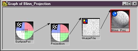
Now open the Surface Point in the Appearance Editor, like we did above. Next enter the name of the MTOR coordinate system's Shape node into the Space field. This step is very important, as it defines where the texture is projected in the scene. The shape name is "faceView." Use the following syntax: Now attach the shader to the Maya object. In Maya, select the Maya object. From the
Slim palette, right click on the "Blinn" shader in the palette and select: You can also view the shader network (as seen on the right) by
right-clicking the "Blinn" shader and selecting: |
|
|
|
7 - Render the Image |
||
|
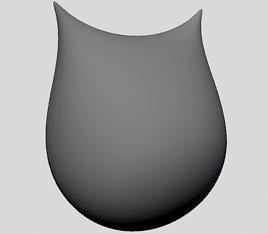
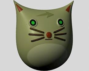
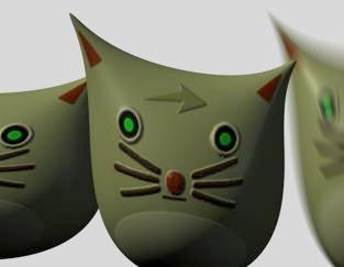
You're ready to render. The rendered image should look similar to the one on the right, with one exception. There is no bump (which we'll get to in a minute), but this is how basic project works! |
|
|
|
Or to make things easier on yourself, just open Final_kitty.ma and see how we did it! Tip: To try it yourself use the network on the right as a guide. For extra credit, connect both the Blinn and the Displacement Shader to an Ensemble. Then attach the Ensemble to the object. That's it! What follows are some workflow issues. |
|
|
Creating Images for Projection |
||
|
||
|
1 - Creating Projection Image |
||
|
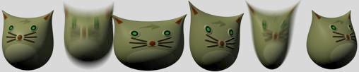
The coordinate system as a camera! We can take a rendering from it. Paint that render in our favorite software paint package, and then project back onto the model with uncanny precision. Here the steps of the workflow are exposed. |
||
|
2 - Set Up Coordinate System as a Camera |
||
|
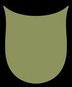
First, open the "Display" tab of the RenderMan Globals. To set up a coordinate system as a camera, enter the name of its shape node in "Camera Name". In this case, "faceView" is the name we renamed our shape node. We'll enter that as the camera. Next define a "Display Resolution" for the image that will be rendered. In this example, the coordinate system has a 1:1.2 ratio so a good resolution is 300 x 360. When rendered, the image renders from the perspective of the "faceView" coordinate system. This results with this image. |
|
|
|
3 - Using Ambient Lighting |
||
|
When rendering images to paint, sometimes it is helpful
to use flat, ambient lighting. With this technique, the colors of the rendered
image will appear as absolute RGB values, which becomes especially useful
for precisely matching colors or patterns in a 2D paint program.
Next paint on it. |
|
|
|
4 - Paint Face in 2D Paint Package |
||
|
Open the rendered image in a 2D paint program, and paint
a face for the color map. Use an alpha channel to mask out non-essential
elements of this texture.
|
|
|
|
5 - Project Image Maps Back to Model |
||
|
Next take your painted textures and project them
back onto the object, using the methods shown above. |
|
|
|
6 - Summary |
||
|
Coordinate systems are helpful for texturing a 3D model
with 2D image maps.
|
 |
|
Projection Note- Tips & TricksTips and tricks for working with projections Note A - Streaking Artifacts |
||
|
Here the image map has been moved to the side of
the head specifically to show the artifacts caused by streaking when pixels
falloff the edges of objects.
|
|
|
|
Note B - Creating textures that stick when deforming |
||
|
There are two methods to create sticky textures, textures
that will move with a surface as it deforms.
|
|
|
|
Note C - Slim Shading Networks |
||
|
For more info on building projections into shading networks, take a look at the projection
recipe under the Shader
Design section.
|
||
|
Pixar Animation Studios
|
 Basic Texture Projection